Background
About the Authors
Calin Gavriliuc: Engine Programmer
Jonathan Bourim: Graphics Engineer & Engine Programmer
We are Computer Science students at the DigiPen Institute of Technology, and have been working on game projects together for several years.
Here are some games we have worked on:


Introduction
Project Cleanser is a year-long team game project that we’ve been working on together. It’s a sandbox game set on a large planet, where the player hunts, digs, and upgrades their equipment to challenge the core at the center of the world.
While we were brainstorming ideas for our new, year-long game project, we encountered many interesting videos showcasing voxel techniques, such as procedural world generation and deformation.
Inspired by Astroneer, we decided to implement a similar method of terrain generation and deformation for our project.
What Is It
Voxels
Voxels are a volumetric representation of a point in 3D space. While pixels are representative of data in a small area, voxels are representative of data in a small volume. These values exist on a 3D grid, and have each point in that grid set to a value. With our goal being to make terrain, we used these values to determine the density of the terrain at that point.
Density for our volume means it exists in one of two states, filled (part of the ground), or empty (air).
Cube Marched Terrain Generation
The marching cubes algorithm is a fast way to generate a polygonal mesh from a height/density field. This algorithm is used to generate triangles for a mesh from a density field. It is a relatively simple, fast, and efficient algorithm that has been used in many applications.
The end result can be seen in the following video.
Goals & Constraints
For our terrain to function in our environment, we constructed our systems with several priorities in mind:
- Multi-threading
- Load Balancing
- Dynamic Loading
- Determinism / Seeding
- Spherical Terrain
Multi-threading:
- Due to the number of math operations that occur when our terrain is generated or modified, performance is the primary concern of this implementation.
- We must leverage Unity’s Job system for multi-threading to maximize the performance of our terrain generation.
Load Balancing:
- As we are generating terrain for a game, it is important to load terrain quickly but also throttle operations as to not overload the user’s hardware and reduce FPS to an unplayable level.
Dynamic Loading:
- Our world is a large, planet-like, environment. As voxels are stored values representing our world, those values must be stored somewhere.
- We quickly approach the limitations of modern hardware if we store all of these values in our active memory.
Determinism / Seeding:
- We generate terrain with the use of randomization tools such as noise functions. With that, there is a decision between a uniquely generated new world, and a randomly generated world that is made consistent by the seed that it is given.
- Our target was the consistent world, as it allows us to leverage Unity’s editor to place objects into our world non-procedurally.
Spherical Terrain:
- As our world is a spherical planet, we needed the ability generate terrain in a radial manner. This includes developing a spherical, mountainous, surface with a cavernous core.
Implementation
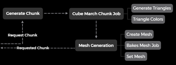
The following is a simplified overview of the pipeline: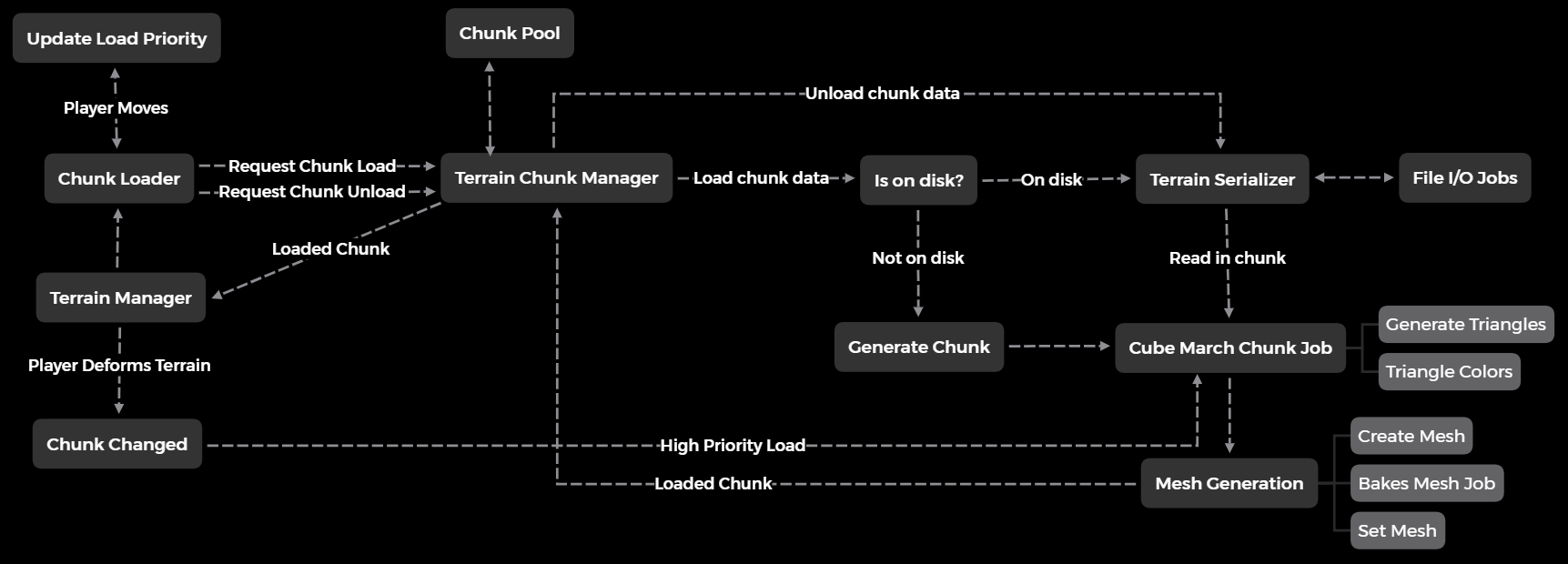
Chunks
In the above examples, we have shown visual representations of our density values, but what is assigning them their mesh and position in the world?
We use a type we call Chunks to store this data and to pass it through our pipelines. In essence, a chunk is a single cube that contains a batch of voxels in the world.
Chunks contain the following information:
1 | // Chunk coordinate |
The data buffers are using Unity’s Native structures (C++ InterOp) to allow us to make use of the Burst Compiler.
Marching Cubes Algorithm
Triangulation
As mentioned above, the marching cube algorithm utilizes voxels to determine the density of a particular volume. This is interpreted as whether or not that point is part of the surface of our terrain. If we take the base case, a single voxel, we can look at its corner points to determine the triangle configuration of the cube that the voxel encompasses.
There exist 2^8 triangle configurations. Some can be seen below:

The orange points at the corners indicate that they are part of the ground, while the empty corners are air. If we extend this idea to a larger grid, these triangles will connect with one another to form the basis of the terrain depending on the configuration of these values.
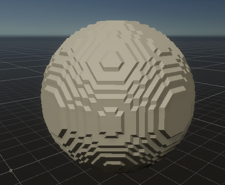
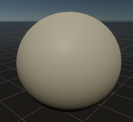
The above image was constructed by setting all the voxels’ density values within a spherical radius of the center of the sphere to +1 (ground / filled state), and outside of the radius to 0 (air / empty state). The algorithm considers the transition between the ground and the air to be where the surface manifests, which is why our surface is a radial shape from the center of the sphere.
Smoothing
You get a blocky sphere when you treat your values as a boolean, either representing a value below the surface or above it. However, if we use a gradient of density values from one voxel to the next, we can utilize interpolation to alter the angle of the triangles we are constructing.
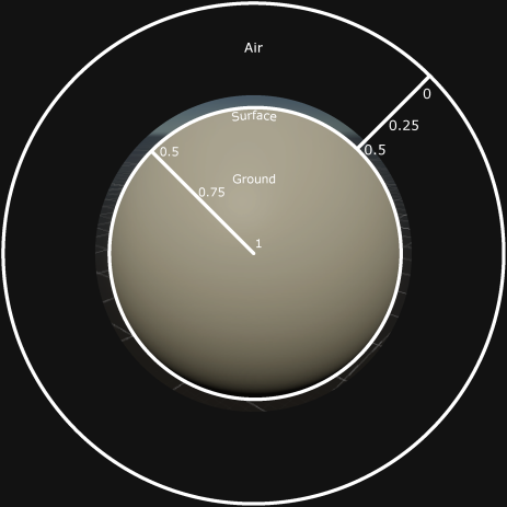
Smoothing Method 1:
One method of doing so is by setting the density values to a gradient ranging from +1 to 0, where +1 is the center of the sphere, 0.5 is the surface, and 0 is the boundary of our voxel grid. In this case, the boundary would be 2 * radius or the diameter of the “world sphere”.
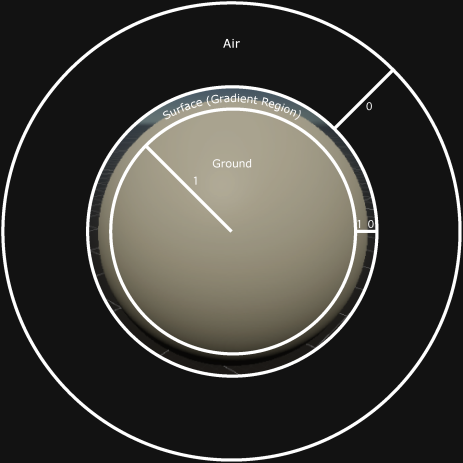
Smoothing Method 2:
Another method of achieving this effect is through a similar technique. Instead of treating the whole “world sphere” as a gradient, only treat the region around the surface as a gradient. This becomes especially useful when applied in a game setting since most nodes are either 1 or 0 and not a floating point value.
Final Result:
Regardless of which method is chosen, you get the following:
This diagram shows how a surface is interpolated between two vertices with varying density values.
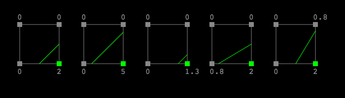
Image Source
The following interpolation code, will achieve the smoothing shown above:
1 | // Smooths densities between 0.0f and 1.0f |
Chunk Generation
Now that we have our data container, and a method to convert that data to a mesh, we need to populate the container with data. Upon being requested, the chunk’s density values are generated and the chunk goes through a two-step process of executing the marching cubes algorithm and mesh construction.
Stitching and Sharing Chunk Edge Data
In a multithreaded environment, it is important to package chunks as self-contained structures as to prevent read & write race conditions between threads. Since the cube marching algorithm generates triangles for the regions between nodes, voxels, it is not trivial to split up a 3D space into chunks of nodes.
The solution to this is to share data between chunks in some way. In our case, we went with duplicating node in the positive x,y,z axis. This was a memory vs multithreading complexity tradeoff.
With this system, we needed to be careful when modifying shared nodes between chunks. An example of where one would need to be careful with duplication of data is deformation. If you deform on the corner of several chunks sharing an edge at inconsistent rates, that would break the consistency of the duplicated values. What results visually is a tearing effect, a gap in between the chunks. This requires additional attention to the synchronicity of the logic operating on the voxel data.

Duplicated edge data also comes with the requirement of having to edit chunk edges only when all neighboring chunks are loaded as well.
Chunk Terrain Generation
Coming Soon
Chunk Loading
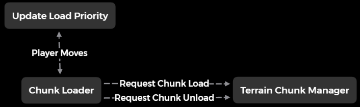
Now that we can generate chunks that also look like interesting terrain, we need a way to selectively pick which chunks to load as to not overwhelm a user’s computer with generating an entire world and expecting it all to fit in their RAM. We call this chunk loading. Similarly, this is also applied to unloading chunks.
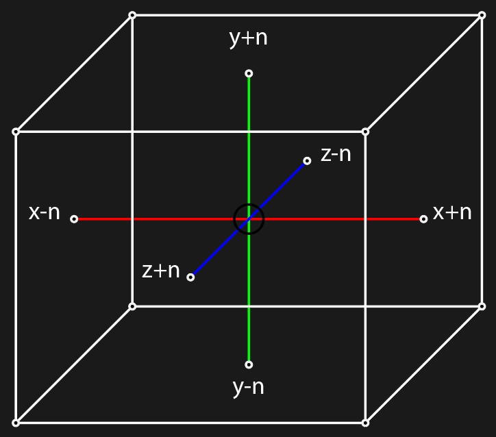
We do this by loading a 2n by 2n by 2n cube around the player. You can take n number of chunks in each axis ([x+n, x-n], [y+n, y-n], and [z+n, z-n]) outward from the player and request them to be loaded.
Similarly if a loaded chunk falls outside of this cube, unload it.
When loading and unloading chunks, it was important to remember that chunks share edge data so borders of chunks cannot be edited without neighboring chunks being loaded first to preserve this “synced” state.
Initial implementations of chunk loading a small region around the player produces the following:
Chunk Serialization
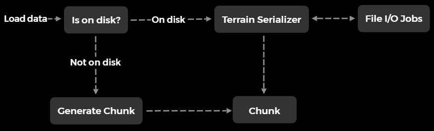
For our implementation, we used a simple approach for storing chunks to a file. Given a known size of a chunk (n by n by n nodes), we can read and write entire 3D arrays of data as their binary representation. This is done for both the density and resource values.
It should be noted that, as a trivial form of optimization, only chunks changed by the player are saved to the disk. Since our terrain generation is deterministic and faster than loading chunks, it is faster to re-generate the chunk on request compared to loading that chunk from the disk. This, in return, also saves on disk space.
These load and unload requests are performed within Unity Jobs to further utilize the player’s CPU cores from a multithreaded approach and to keep consistency with the rest of the systems.
Performance
Due to real-time gameplay restrictions and the amount of terrain a player is required to load, chunk generation/loading/marching needs to be highly optimized.
As this is one of the most performance-critical portions of our game, we use Unity’s Job system to multi-thread the execution of this code. Originally, we had experimented with compute shader pipelines, which are faster in normal circumstances. However, after performance testing, Unity’s Burst Compiler in conjunction with the job system has outpaced these compute pipelines due to the overhead of large data buffer I/O with the GPU. The overhead of I/O was larger than the time for operations to be performed on that buffer, ultimately resulting in CPU-based computation being faster.
Optimization
Major sources of optimization:
- Chunk Stages
- Cross-Frame Work
- Maximizing Usage & Throttling
- Priority Queueing
- Level Of Detail (LOD)
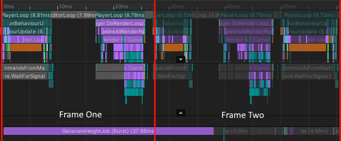
The following is frame-by-frame profiling of the chunk processing system using multiple distinct job stages and cross-frame job completion of the chunk request pipeline (after optimization):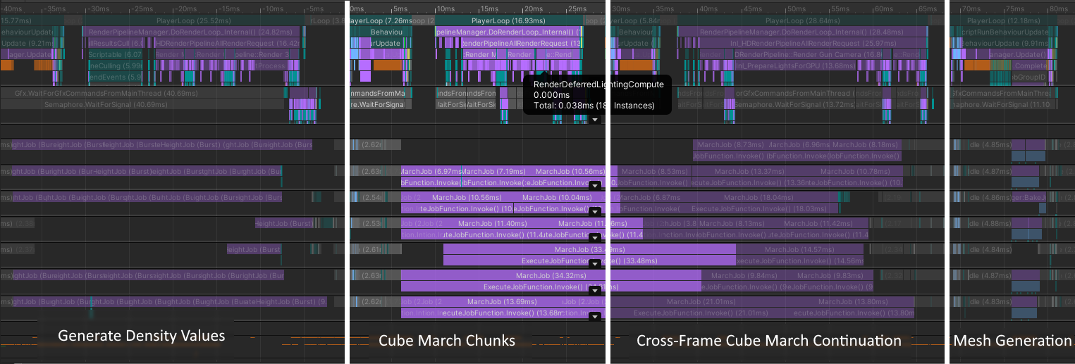
You can see the main thread running horizontally across the top, and seven more threads running the jobs in parallel - in this case.
Chunk Stages
Key Terms:
- Frame: One game processing frame / update loop.
- Work State: One of three stages a chunk will go through to be processed fully.
- Work State Loop: One loop of all three work state steps.
Our system uses three work states for processing chunks. These work states only allow a certain type, and by extension a certain amount, of work to be done on chunks for any given grouping of frames.
This technique greatly reduces lag spikes a user will experience from loading chunks.
If a work state is completed early, the system will move on to the next work state without waiting for the full-frame count.
For any given frame, only process one of three work states:
1 | // Do the required work for this frame |
Provided is a visual example of breaking up two sets of jobs across two frames:
It should be noted that, despite this optimization being applied, the nature of this game requires some chunks to be processed immediately. For example, if a player deforms/destroys part of the terrain, the changed chunks must be processed immediately as to not produce visual lag to the user. These chunks are “fast-forwarded” through this system and are processed within one frame.
Cross-Frame Work
Key Terms:
- Processing Spike: A period of higher stress on the CPU, often causing visual lag/“jumps” to the user.
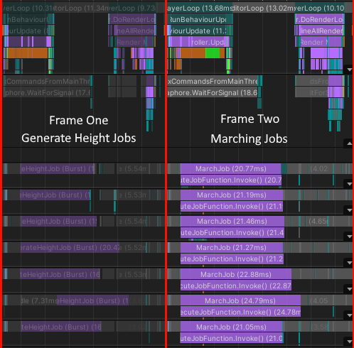
In general, each work stage will take a maximum of three frames. This technique gives jobs the ability to span across multiple frames, if needed, causing processing spikes on the CPU to “average out”.
After allowing cross-frame jobs, after this optimization is applied, you can see the job (GenerateHeightJob in purple) running across two game frames as to not hold the main gameplay thread:
Maximizing Usage & Throttling
Key Terms:
- Job’s Average Processing Requirements: The amount of work/time a given job takes/requires when being processed by the CPU. Generally, this is a rough estimate.
As with the previously mentioned techniques, it is important to maximize usage of the CPU while also not overloading it. Given a set of chunks to be processed, instead of computing all of them in one go, breaking up that set into batches based on CPU speed / CPU core count / a job’s average processing requirements is a good way to determine how many chunks to process in one complete work state loop.
This optimization technique is most effective when the user loads many chunks at once, such as when they first load the world.
The following image shows all chunks around the player being populated with height values in one go:
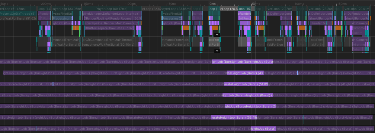
While this maximizes CPU usage, this ends up halting any single chunk from loading/rendering for a player until all chunks have been processed - which far from ideal. This also has the side effect of preventing those threads from being used by any other job(s) during their processing.
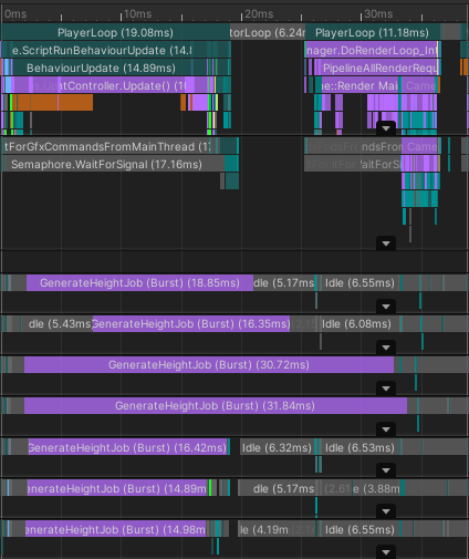
Instead, using a per-frame burst of one-job-per-thread (or more, depending on a job’s average length) paradigm allows for maximizing thread usage without blocking other jobs or preventing rendering/loading.
Using one job on each thread in per frame, a much more reasonable result is produced:
Priority Queueing
Key Terms:
- High Priority Chunk Request: A chunk that needs to be processed by the end of the current frame.
- Low Priority Chunk Request: A chunk that needs to be processed as fast as possible, with minimal lag.
Deciding which chunks should be processed first was briefly mentioned above with fast-forwarding, but it is, in reality, more complicated.
Once a chunk is requested (either high or low priority), the system then sorts it into a queue based on current queued chunk priorities and will update priorities each frame, as needed.
The following is a general set of rules we followed when implementing chunk processing priority queueing:
- High priority chunks:
- No need to sort these requested chunks as they are all processing that frame.
- Always pulled from the queue by the system before low priority chunks
- Low priority chunks:
- Sorted by a weight which is usually the squared distance to the player as these chunks usually come from chunk loading
- Pulled from the queue by the system when there are not enough high priority chunks to process
The following code reflects these set of rules:
1 | // Grab high priority chunks (processed this frame) |
A rough example of 2D priority queueing, a cross-section of the 3D chunk loaded cube, is demonstrated as an interactive demo below. Move your cursor around to see which chunks have priority to be loaded relative to your cursor.
Note: This demo’s source code does not reflect the project’s implementation. It is purely for a visual understanding of the chunk loading concept.
The maximum number of chunks a three-stage loop can process is given by the following:Max(Number Of High Priority Chunk Count, Number Of Reasonable Chunks Per Stage Loop)
That is to say that high priority chunks are always processed with low priority chunks filling in any free slots in CPU cores.
Using a priority queue and updating weights as needed, you get responsive chunk loading that can adapt quickly to, for example, changes in player position:
Once applying a similar technique to chunk unloading, you get fluid and responsive terrain.
Level Of Detail (LOD)
Key Terms:
- Level of Detail: Also known as LOD, it is the amount (level) of data (detail) you are choosing to display to the user. This is often used on far-away objects since it is the same to the user visually but faster to compute.
Given our grid-based voxel terrain, LOD was trivial to implement on a basic level. Since our chunks are 16x16x16, LOD can be a power of two to reduce the amount of data that needs to be computed/rendered out of this chunk.
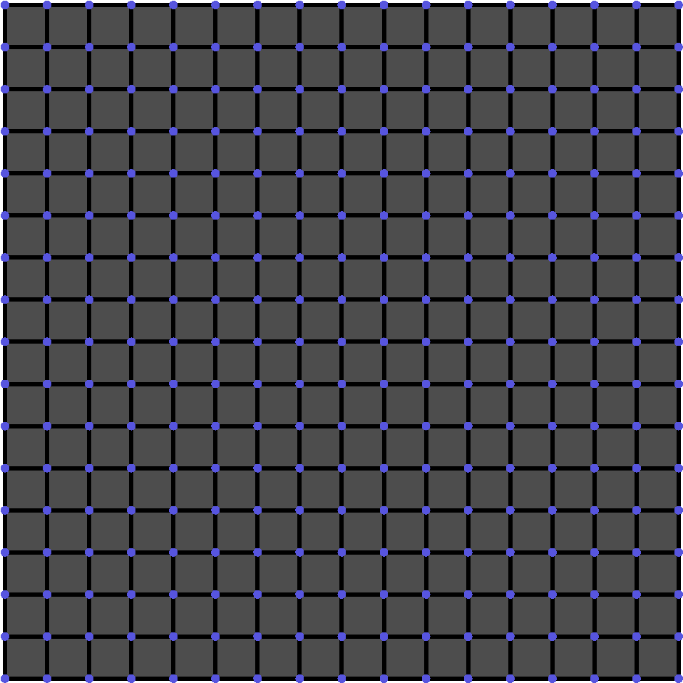
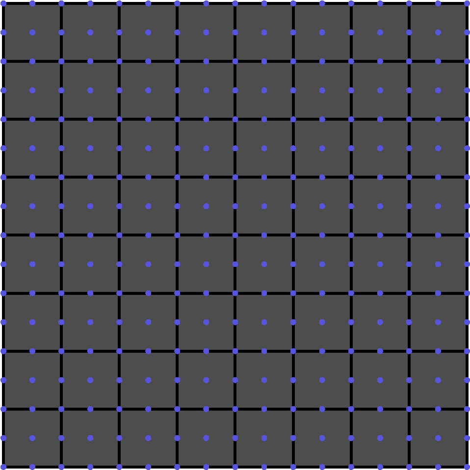
As a simple example, take the following 2D grid of 16 voxels, 17 nodes:
Key:
- Purple Circles: Density data nodes.
- Black Squares: Voxels generated from corner nodes.
| LOD of 1: | LOD of 2: | LOD of 4: |
|---|---|---|
 |
 |
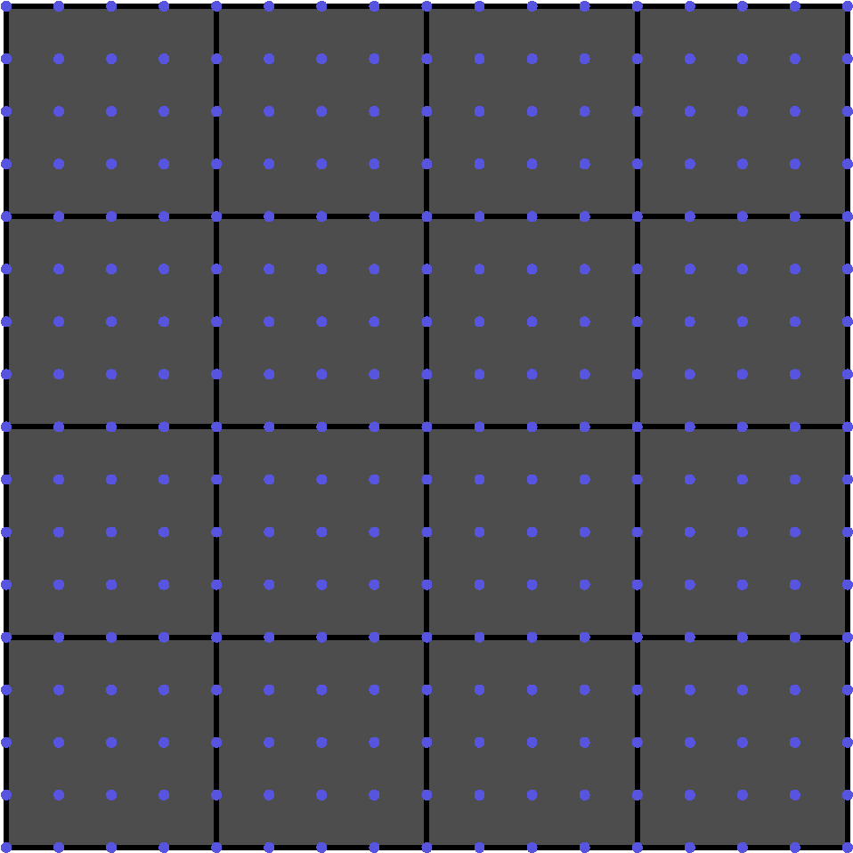 |
As can be seen, voxels sample from fewer nodes, but are scaled to take up the same amount of space.
The LOD gradients shown below demonstrate this logic applied to the terrain.
| Smooth Sphere LOD Gradient: | Noisy Sphere LOD Gradient |
|---|---|
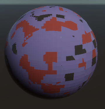 |
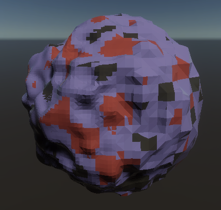 |
Despite promising results, you would need to apply an algorithm similar to TransVoxel to implement a more sophisticated solution that doesn’t generate holes between differing LOD levels. As of currently, we do not implement this algorithm.
Terrain Features
Terrain / Voxel Manipulation
When we manipulate our voxel terrain, we alter the density values in an area of influence.
In our game, we use a spherical brush to accomplish this, resulting in spherical cutouts of the terrain at the target area.
In the example above, you can see both additive and subtractive operations. Thankfully, these translate straightforwardly to adding and subtracting from the density values in our target area in a radial gradient.
Below is an interactive demo of the logic functioning in a 2D variant. Mouse over the area to subtract or add from a given area, altering the terrain. These values are either 1 or -1, representing a filled or unfilled area, respectively. As there is no gradient, this will result in unsmooth terrain.
Click the left mouse button to toggle addition/subtraction.
Editor Mode
Procedural generation is typically executed at runtime. In other words, our voxel terrain would only be visible upon launching the game into Play Mode.
However, this is problematic in the case where we would like to edit our scene. How would we determine where to place a sign sticking out of the ground, or a treasure chest?
We’d need a way to edit the scene with the world already constructed. Our solution is editor-time world loading.
By using proximity loading of our chunks as found at runtime, we may move the player around in the scene to load whichever portion is needed to us.
We track the current state of the Unity editor to determine when to dispose of the memory or create it anew.
Entering play mode or edit mode will reconstruct the necessary memory for the voxel terrain.